Every part starts as a 3D model and a deadline. Turning that model into metal takes a plan. Right now, that plan mostly lives in one person's head. This post asks a narrower question than “how does machining work”: how much of the planning can a computer do instead, and where does it still break?
A machine shop gets a STEP file (a 3D model) and a due date. Before anyone cuts metal, someone decides how the part gets made: which surfaces to machine, in what order, with which tools, at what speeds, clamped which way, flipped how many times. That document is the process plan, and writing it is still largely a person reasoning through the model from experience.
That person is the bottleneck. A new part adds days to every quote. The planners who are good at this took a decade to get there, and no two make the same calls. Cycle times drift between shops, and between planners, for no good reason.
This article walks through five stages of process planning for a thin aluminum consumer-electronics housing. It's a better test case than a plain block because its features spread across five faces, which is exactly what makes planning hard. Each stage has an interactive example you can play with, but the focus here is the automation: what the classic method was, what the industry uses now, and how well it works.
The 60-second version of the process
CNC machining is cutting, not printing. You start with a solid block (the stock) and a computer-controlled machine carves the part out with a spinning tool. Every cut removes material and none goes back, so the order of cuts is permanent. That single fact is why planning is hard.
A few terms recur:
- Feature: a nameable piece of shape one kind of cut produces: a pocket, hole, slot, rounded edge. The CAD model only stores bare faces and edges; reading those back as features is where planning starts.
- Datum: a reference surface you measure everything else from. Cut it first, locate the rest against it, like squaring one edge of a board before marking the others.
- Setup: how the part is held and which way it faces. Reaching a feature on a different face usually means unclamping and re-clamping in a new orientation (a re-fixture), which costs time and a little accuracy.
The part: a thin aluminum housing, roughly 138 × 67 × 7 mm. A large shallow pocket on the inside face, radiused outer edges, small overhanging ledges inside the pocket that a straight tool can't reach, ports and holes along the bottom edge, and button slots on the long sides.
A process plan is the bridge between the two files that don't describe manufacturing: the STEP solid on one end, the G-code coordinate list on the other. It's an ordered list of operations, each with a tool, cutting parameters, and a fixture setup, plus the datum scheme tying it all to measurable references. Machinists build it by hand because every decision leans on the others: the tool changes the feeds; the order changes what you can hold; a choice that looks fine now can wreck a surface you needed three operations later. Automating it means encoding that web of dependencies, and each stage below is a different kind of reasoning, which is why they got automated at different rates.
Stage 1: Feature extraction
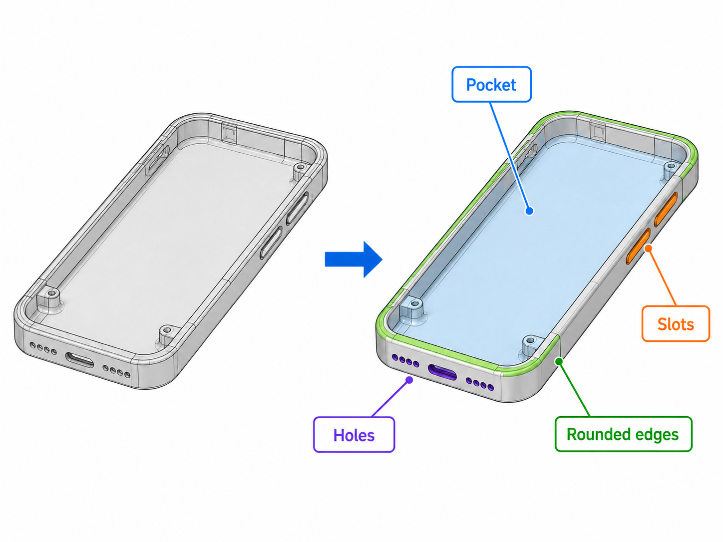
The job: translate raw geometry (faces, edges, vertices) into machinable features (pockets, holes, chamfers, hole patterns). Nothing else can happen until you know what there is to cut.
Stage 1 · interactive example
Feature recognition
Switch between raw B-rep geometry and recognized features, then run the adjacency-based recognizer. The feature-to-face mapping is what forces the housing into five setups.
Give the same recognition system two different parts: a simple bracket and a complex phone housing full of overhangs and ledges. Newer graph neural networks like UV-Net and BRepNet can pick out features straight from the geometry, no hand-written rules needed. AAGNet even separates things like individual pockets instead of lumping them together, which is closer to how manufacturing works.
On clean, synthetic datasets such as MFCAD++, published models report very high recognition scores. Performance drops on manually designed parts that differ from the training distribution. That is the harder phone-housing case: intersecting features, unusual ledges, and geometry the model may not have seen before. BrepMFR (2024) addresses this gap with domain adaptation from synthetic to real CAD data.
Feature recognition works best when parts resemble the training data. Unusual, real-world cases still need review. In practice, CAM tools like CAMWorks, Fusion, hyperMILL, and Esprit still stick with traditional geometry methods. Less exciting, but dependable.
Stage 2: Tool selection
The job: assign each feature a tool that can physically reach and cut it.
Most of the time the tool reads straight off the feature, but the reading is not preference, it's geometry.
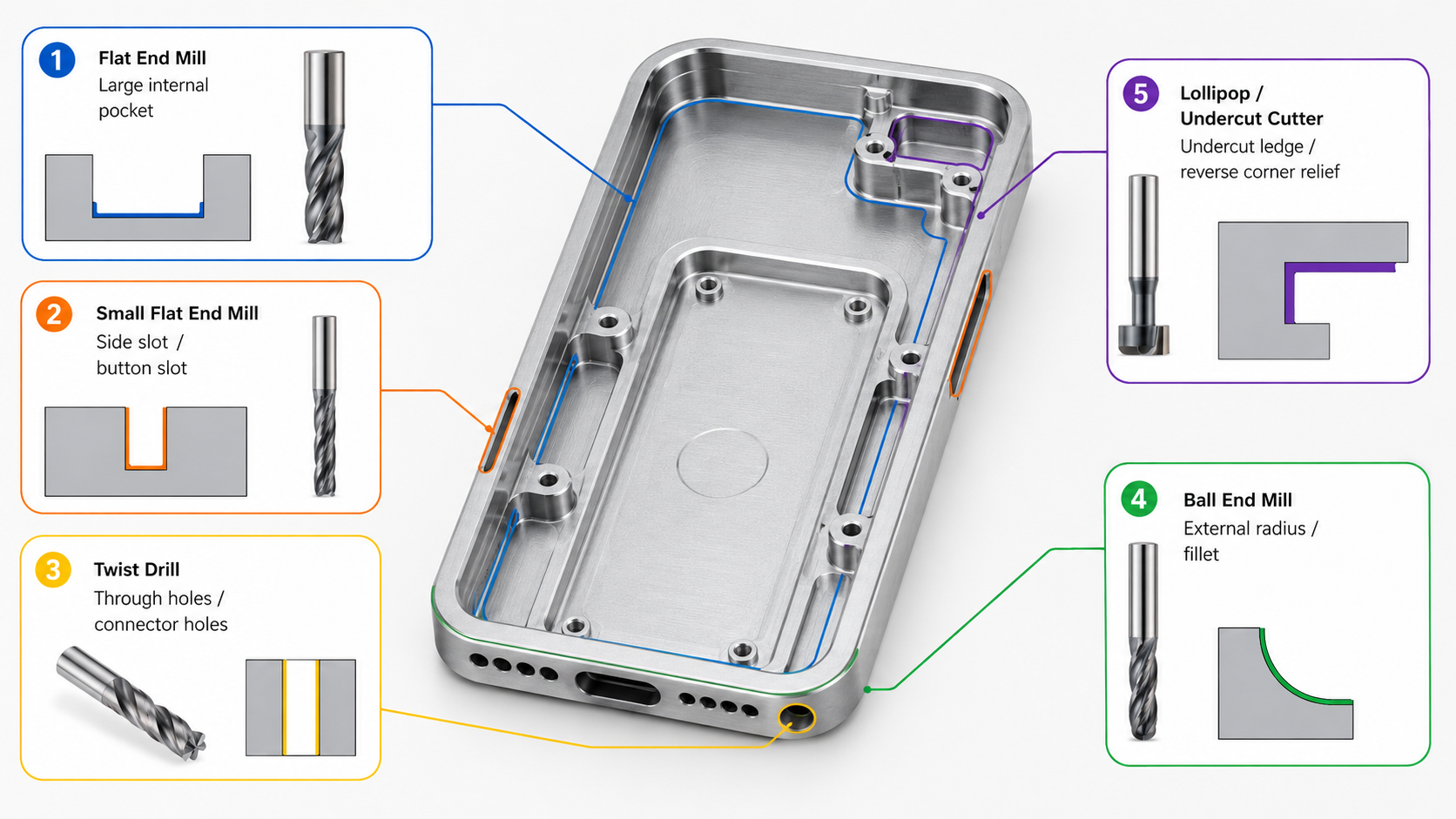
- A flat open face → use a face mill to level it quickly in a few passes.
- A flat-bottom pocket → use a flat end mill; the corner radius limits the largest diameter that fits.
- A round hole to size → drill it when possible; interpolation is slower and usually less accurate, though it can help cover multiple sizes in softer materials.
- Radiused outer edges → use a ball or bull-nose mill; a flat end mill would leave a sharp edge instead of the required radius.
- Overhang ledges → use a lollipop cutter; its reduced neck lets it reach under the lip where a straight tool would collide.
Stage 2 · interactive example
Tool selection
Compare tools against each feature and see why geometry, tolerance, access, and tool inventory change the choice.
This stage is still rule-based. Calling it “AI” is generous. CAM tools like CAMWorks or Fusion see a “flat-floor pocket” and pick the same roughing and finishing tools they’ve used before. It’s basically a lookup table: one feature in, one tool out.
It breaks when rules conflict. A lollipop cutter might be right for an overhang, but the shop may only want six tools loaded, not nine. Now it’s a trade-off between “best tool for this feature” and “fewer tool changes overall,” and current systems don’t handle that. Someone has to decide. Researchers have tested genetic algorithms with neural nets and multi-cutter optimization for complex five-axis parts, but none of it has made it into CAMWorks, Fusion, hyperMILL, or Esprit.
So the lookups are basically solved. The real decision-making, the trade-offs across the whole part, is still stuck in research.
Stage 3: Feeds, speeds, and power
The job: compute the numbers: spindle speed, feed rate, material removed per minute, and the spindle power that takes. Get them wrong and you get a broken cutter or a scrapped part.
The core relationships are simple:
Spindle speed, N, comes from the material's ideal cutting speed and the tool diameter. Feed rate, Vf, builds on that: multiply by fz, the feed per tooth you choose, and Z, the tool's flute count, and you get how fast the tool can advance while each edge takes a proper bite.
From there, feed rate times depth and width of cut gives the material removal rate (MRR), or how much metal comes off per minute. Multiply that by u, the material's specific cutting energy, and you get the spindle power the cut actually demands. Aluminum sits low on that scale; titanium runs several times higher. Whatever comes out has to stay under the machine's spindle limit, or something breaks.
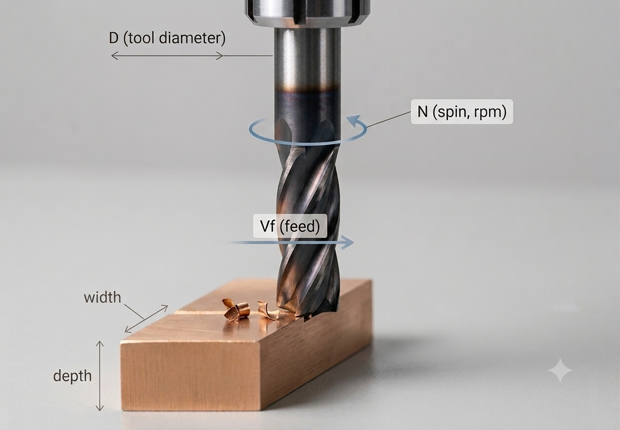
In practice, this isn’t just plugging in numbers. You still need to work within the tool and machine limits, and watch for real-world issues like deflection, heat, and chatter.
Stage 3 · interactive example
Feeds, speeds, and power
Use a 6 mm, three-flute end mill in the housing’s main pocket. Stay within the 12,000 rpm spindle ceiling and the material-specific chip-load window; this light cut remains well below the VF-2SS’s 22.4 kW power limit.
Machine learning is already used in production for cutting-parameter recommendations. CloudNC’s Cutting Parameters AI combines it with a detailed physics model of the cutting process, taking into account things like tool holder geometry, material, and surface finish. It can recommend feeds and speeds for a given toolpath in seconds. That’s a big shift from the old handbook approach, where you’d use the same entry for “aluminum, 6 mm end mill” no matter the situation. CloudNC claims at least a 20% productivity gain, and it can also give safe starting points for tools or materials a shop hasn’t used before.
Academic work is more experimental. Some researchers use reinforcement learning to tune spindle speed and feed rate against cost or energy use. Others combine genetic algorithms with neural networks to optimize cutting parameters for specific materials. These studies are usually limited to a controlled setup with one machine and one material, not a system that can be dropped into any shop.
Stage 4: Sequencing and setups
The job: put the operations in an order that satisfies two goals that pull against each other. This is the stage that resists automation, and the reason process planning is still a skilled job.
Stages 4–5 · interactive example
Sequencing and full-process simulation
Reorder the operations and watch the violation count (broken datum rules) and setup count. Then run the same plan end to end in 3D.
Two forces:
- Datum precedence (a hard rule). A reference surface must exist before any feature measured from it, and a later cut must never remove a surface an earlier op relied on. Face the back first to set the primary datum, then reference everything to it.
- Setup minimization (an optimization). The pocket faces up, the ports face off the bottom edge, the buttons face off the two long sides. Every re-fixture costs time and accuracy, so group all work that shares an orientation before you flip.
The first rule is easy for a computer. It's just a matter of checking what depends on what, the same kind of problem as scheduling tasks: fast and solved.
The second rule is much harder. Finding the fewest setups is the same type of problem as planning delivery routes, technically solvable, but slow and complex.
So why hasn't this been automated? Because cutting down setups only makes sense if the part can actually be held safely in each one. Right now, nothing checks that automatically, software just assumes a person already confirmed the part can be clamped that way. CAM software uses a simple shortcut instead: only cut a face's details after the surface it depends on already exists. That's not a lack of ambition, it's that "can this fixture hold the part without damaging it" is something no software can judge yet. Until that changes, this step stays a human job.
Stage 5: Toolpaths, simulation, and the finished part
The job: turn the plan into motion: generate cutter paths, check for collisions, and estimate cycle time.
The demo above shows the idea: as the sequence runs, the part is carved in 3D. You can reorder steps or swap materials and the geometry will still “work,” but in reality, datums and setups are what make or break that sequence.
Under the hood, this stage is already solved in a very traditional way. Adaptive toolpaths handle corner overload by keeping a constant engagement (around 30–45% of tool diameter) instead of cutting full-width through every turn. Systems like Fusion’s Adaptive Clearing or Mastercam’s Dynamic Milling do this with straightforward geometry: offset the stock, then generate a path that maintains engagement. No AI involved, just math.
Simulation follows the same pattern. The stock is broken into small columns and material is subtracted as the tool moves; if anything goes negative, it flags a gouge before machining.
AI could predict chatter or tool wear from past jobs, but it has not gained the same traction here. The reason is simple: this part already works. Toolpath generation is deterministic, and the current methods are reliable enough that there’s little pressure to replace them.
The pipeline, and why it automated unevenly
Put the stages together and you get a chain of different reasoning types:
| Stage | Kind of reasoning | Automation maturity |
|---|---|---|
| 1. Feature extraction | Geometric pattern matching | High on common parts, unreliable on the long tail |
| 2. Tool selection | Rule base + global optimization | High for the rules, human for the trade-offs |
| 3. Feeds / speeds / power | Physics + material data | Moving from tables to physics models |
| 4. Sequencing & setups | Constraint satisfaction + setup search | Lowest: workholding stays human |
| 5. Toolpaths & simulation | Computational geometry + sim | Effectively solved, shipping |
The plan is only as good as the weakest link, and the links feed each other in both directions: sequencing depends on tooling, tooling depends on how the part is held, which depends on sequencing. That circularity is why nobody automated the whole thing at once. Each stage got picked off separately, and how far each fell tracks how clean its formula or pattern is.
Why vibe coding struggles with CNC
We pointed Codex and Claude, two popular tools for vibe coding, at the entire CAD-to-CAM-to-CNC pipeline. The brief was direct: build a program that takes a STEP file and produces a usable process plan. We tried repeatedly rather than relying on a single one-shot run. Every version failed along the same boundary. The tools handled geometry, arithmetic, and table lookups. They came apart when the plan required judgment.
Four failures kept recurring:
- Plausible before correct: one run emitted a complete G-code file, including setups and spindle speeds, whose first lines read "NOT VERIFIED FOR USE ON A REAL MACHINE." It looked finished and read like a process plan, but the confident formatting sat on top of shaky substance.
- Unusable instructions: the generated program dropped geometry it could not handle. On the die model, the rounded edges were present in the CAD file but never reached the toolpath. Only the 21 pips were cut. A plan that quietly skips features cannot be handed to a machinist and run.
- No generality: a STEP file contains faces, edges, and vertices. It does not label a shape as a pocket or a hole. Every parser locked onto the part used during development. One version was hard-wired to a single phone-case model, with baked-in half-extents of 38.5 and 76.5 mm and an assumption that the importer returned exactly three meshes. Another refused to run unless the bounding box was a perfect cube. Change the geometry and the program broke, so the code had to be rebuilt for each part.
- Precision ignored: feeds, speeds, and tolerances came from generic textbook tables that the program's own notes described as representative values, not a verified tool library. It skipped the physics that decides whether a cut survives, including deflection, chatter, and workholding.
Intersecting geometry, thin-part workholding, and cutting physics without a closed-form answer force a general-purpose model to fill gaps. A fluent answer can hide those gaps. Checking the output still requires a real machine, verified CAM software, or someone who has cut similar parts. Those were the very things the generated program was meant to replace.
We would not trust these programs with expensive stock and tooling. Our tests showed that current general-purpose coding models do not yet solve arbitrary 3D geometry and CNC process planning.
A fluent plan and a workable plan look identical on screen. The difference appears at the spindle, or to a planner who has already watched that mistake happen. Vibe coding can draft routine work in seconds, but risky decisions still need a person, real hardware, or verified software to sign off. Skip that step and the machine will find the mistakes for you: broken tools, scrapped stock, wasted hours, and material bought twice.
Where the money and the products are
Two markets grew up around this, attacking different ends.
Inside the CAM software the programmer already uses. The long-running version is feature-based, knowledge-based machining: CAMWorks, Fusion, hyperMILL, Esprit recognizing features and applying saved strategies from a technology database. The newer version is AI-assisted:
- CloudNC's CAM Assist generates 3-axis and 3+2-axis strategies from the model. CloudNC's public claim of up to 80% less CAM programming time is a time-reduction metric; its separate “70–80% complete” language describes the completeness of a generated first pass. The figures are related, but they are not the same measurement.
- CAM Assist 2.0 launched in September 2025. At launch it initiated from Fusion and Mastercam, with NX available shortly afterwards. The release added more feedback and step-by-step control; our reading is that this positions the AI as a strong first pass for a programmer to review, rather than as a finished program. Current compatibility should be checked against CloudNC's live product list.
- The shop-floor reality is mixed. Earlier forum accounts and trials reported programming-time savings around 20–40% after finishing passes, deflection, and witness lines were corrected. Those are anecdotal observations, not a directly comparable test of CloudNC's headline metric, and pre-2.0 experiences should not be treated as a verdict on the current release. They reinforce a practical point: output quality depends heavily on a well-configured tool library, setup, and review process.
Attacking the quote directly. Upload a model to Xometry, Protolabs, or Fictiv and get pricing, lead time, and design-for-manufacturability feedback in seconds. Xometry's engine runs computational-geometry algorithms that read a part's features and complexity the way an expert would, layered with machine learning trained on a large history of real jobs and a supplier network of 5,000+ shops. Tools like aPriori and Paperless Parts do the estimating side for shops that quote rather than buy.
Investment is following the same direction. On 7 May 2026, Siemens announced an approximately $50 million minority investment in Xometry alongside a partnership intended to integrate manufacturability, pricing, sourcing, and lifecycle intelligence into Siemens' Designcenter software within Xcelerator. It is announced integration, not a shipped product, but the direction is clear: bring manufacturability and price feedback into design earlier.
Limitations and the pattern in the failures
The failure modes share a pattern:
- Feature recognition breaks on intersecting geometry, including the housing's overhang ledges. Learned models also lose accuracy on real parts outside their training distribution.
- Rule bases are brittle and need a specialist to maintain.
- Every stage assumes clean input: a model missing its tolerances poisons the plan.
- Fixturing and workholding: clamping a thin shell through five orientations without distorting it is barely automated and stays human. On this part, it's most of the work.
- Cutting physics (deflection, chatter) resists closed-form answers.
- The long tail starves the ML approaches of training data on unusual parts.
Sequencing sits underneath most of these. It is the stage that carries the judgment, where a valid answer and a good answer diverge. The same ordering shows up in any field where expert judgment gets encoded: geometric reasoning, then rules, then physics, then optimization, then learning. The stages with a clean formula or pattern go first; the stage that integrates all the others under constraints nobody wrote down goes last.
For CNC, the practical near-term tool drafts routine operations in seconds and hands uncertain decisions to a machinist. That is roughly where the market has settled. The quoting bottleneck gets shorter. It does not disappear.
What this means for a growing job shop
For a European job shop with 30 to 60 people, the opportunity is larger than adding another CAM plug-in. Start with input quality. A job may arrive as a PDF drawing, an incomplete model, tolerance notes in an email, and a familiar customer's unwritten expectation. Before CAM can choose a toolpath, someone has to extract that information, resolve ambiguities, and decide what must be queried. A clean model is valuable, but it is only one part of a CAM-ready job packet.
Next comes knowledge capture. A senior planner knows which fixture survived a similar thin-wall part, which cutter works on a particular machine, and where a drawing is likely to conceal a risk. That knowledge is often distributed across old programs, setup sheets, emails, and one person's memory. Making it searchable and reusable does not replace the planner. It lets the planner review exceptions instead of reconstructing every routine decision, and it reduces the exposure when an experienced employee retires or is unavailable.
The same information feeds the quoting loop. Marketplace tools help buyers obtain an instant price, but a shop still has to decide whether a job is feasible, which setup assumptions drive the cycle time, what material or tooling risk is hidden in the request, and whether the margin survives after rework. Connecting intake, drawing extraction, historical jobs, and engineering review can shorten that loop without pretending that a price is certain before the part is understood.
AAI Labs designs practical AI workflows around the information a shop already has, from PDF and email intake through knowledge retrieval and quote preparation, with a human engineer retaining approval at the decisions that carry technical or commercial risk. Talk to AAI Labs about making your planning and quoting workflow more resilient.
Notes and references
- Part and process-plan exercise follow MIT 2.008, Design and Manufacturing II, Spring 2025, HW2 Problem 3, and Lecture 6 on CAD/CAM and process planning (MIT OpenCourseWare).
- AAG feature recognition: Joshi, S. & Chang, T.C., “Graph-based heuristics for recognition of machined features from a 3D solid model,” Computer-Aided Design, 1988.
- Learned feature recognition & benchmarks: UV-Net (Jayaraman et al.), BRepNet (Lambourne et al., 2021), AAGNet (Wu et al., 2024), BRepGAT (Lee et al., 2023), BrepMFR (2024); datasets MFCAD, MFCAD++ (~60k models), and the real-design Fusion 360 Gallery. Synthetic-vs-real accuracy gap drawn from published segmentation results (≈99% synthetic vs ≈80% on real designs for comparable models).
- Cutting-speed/feed windows and specific cutting energy: Kalpakjian & Schmid, Manufacturing Engineering and Technology, Tables 24.2 and 21.2, used as representative data, not a verified tool library.
- Machine limits: HAAS VF-2SS, 12,000 rpm, 22.4 kW spindle.
- Industry tools (as of mid-2026): CloudNC CAM Assist 2.0 launch and compatibility information (September 2025), CloudNC's programming-time and completion claims, and public machinist-forum discussions of earlier versions. Xometry Instant Quoting Engine and DFM AI; Siemens' 7 May 2026 partnership announcement describes the intended Designcenter integration and approximately $50M investment.
- The five embedded tools are simplified for teaching. Cutting data uses representative values to show relationships; the 3D part is assembled from primitives rather than a true boolean solid.